
Navigation Equipment

Navigation Equipment
Objective: the student will be introduced to navigation systems. The student will also review known systems
Completion Standards: the student will be able to explain the different aspects to the navigation systems. The student will also be able to explain how an ILS system works
References: PHAK ch16, IFH ch9, Part 91, AIM
Equipment: White Board and markers, iPad/ computer
IP’s Actions:
Assess student
State the objective and completion standards
Writes down references
Provide attention getter
Present content
Assessment
Assign Homework
SP’s Actions:
Take notes
Ask Questions
Introduction:
(Attention Getter) : (Link goes here)
Motivation: (Discuss purpose for lesson and relate to Attention getter)
Overview:
One ground-based navigational system
Distance Measuring Equipment (DME)
Satellite-based navigation
Instrument landing System (ILS)
Transponder
Autopilot
Content:
One ground-based navigational system (VOR/VORTAC, NDB, and DME).
VHF Omnidirectional range
VHF-radio-transmitting ground station
Projects straight-line courses (radials) from the station in all directions.
Radials projected with reference to the magnetic north.
Radial
a line of magnetic bearing extending outward from the VOR station. Accuracy of course alignment with radials considered to be excellent (within ±1°).
Projection distance depends on power output of the transmitter.
VOR ground stations transmit within a VHF frequency band of 108.0-117.95 MHz.
Signal transmitted is subject to line-of-sight restrictions.
Range varies in direct proportion to altitude of receiving equipment.
CONE OF CONFUSION
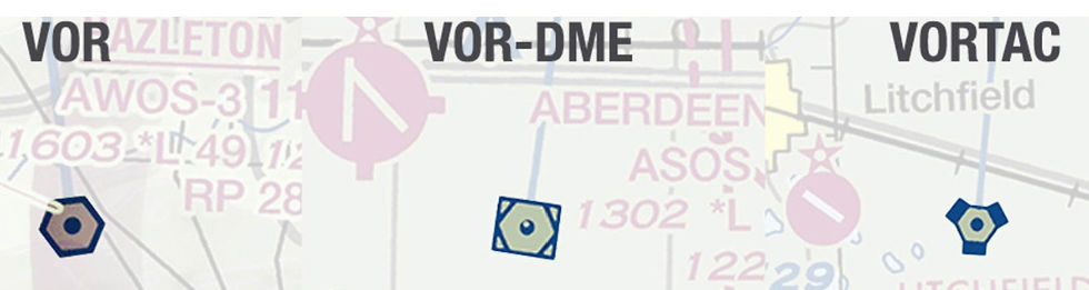
Types
VOR
The VOR by itself, providing magnetic bearing information to and from the station
VOR/DME
When Distance Measuring Equipment (DME) is also installed with the VOR.
VORTAC
When military tactical air navigation (TACAN) equipment is installed with the VOR. DME is always an integral part of a VORTAC.
VOR Classifications (AIM 1-1-3, 1-1-8)
Classified according to operational use—three classes with varying normal useful ranges.
T — terminal
L — low altitude
H — high altitude
VL — Low VOR PBN (Performance Based Navigation)
VH — High VOR PBN
VOR MON (Minimum Operational Network) {1-1-3 (f)}
FAA is removing selected VOR’s From service
Being replaced with PBN (Performance based Navigation)
Primary GPS Systems
Those not equipped with DME/DME Avionics can use VOR MON
Class | Altitudes | Radius (Nautical Miles) |
T | 12,000’ and Below | 25 |
L | Below 18,000’ | 40 |
H | Below 14,500’ | 40 |
H | 14,500 — 17,999’ | 100 |
H | 18,000’ — FL 450 | 130 |
H | FL 450 — 60,000’ | 100 |
VL | Below 5,000’ | 40 |
VL | 5,000 — 18,000’ | 70 |
VH | Below 5,000’ | 40 |
VH | 5,000’ — 14,500’ | 70 |
VH | 14,500 — 17,999’ | 100 |
VH | 18,000’ — FL 450 | 130 |
VH | FL 450 — 60,000’ | 100 |
VOR checks (91.171)
Periodic checks and calibrations
Not required for VFR flight, but the best assurance of maintaining an accurate VOR receiver.
Verifies that the VOR radials the equipment receives are aligned with the radials the station transmits. Checkpoints are listed in the Chart Supplement.
FAA VOR test facility (VOT)
Certified airborne checkpoints
Certified ground checkpoints located on airport surfaces
Airways
Dual VOR check
IFR tolerances required are ±4° for ground checks and ±6° for airborne checks.
Components
Ground transmitter
The ground station is at a specific known location on the surface, and it transmits on an assigned frequency.
Airborne receiver
The receiver in the aircraft can tune that frequency and has a means to display information from that signal.

Using the VOR
The VOR is a radio receiver
Is tuned to the frequency of the VOR station to be used.
The station can be identified by a Morse code identifier, or a voice telling the name of the station.
If the VOR is out of service, the identifier is removed, and the absence of an identifier means that the station should not be used for navigation.
Can have an alarm flag to indicate when the signal strength is too weak (because the aircraft is too low, or two far away, or is out of the line-of-sight of the station) and should not be used for navigation.
Finally, even if a Morse code is detected it should be confirmed that the VOR is not broadcasting the Morse for "test", as this is sometimes also done. If in testing a VOR should not, obviously, be used for navigation.
Flight Deck Instruments

These cockpit instruments relate the following information to pilots:
Which radial the airplane is on or,
Amount of deviation from the radial selected, and
If the selected radial will take the pilot closer TO or further FROM the VOR
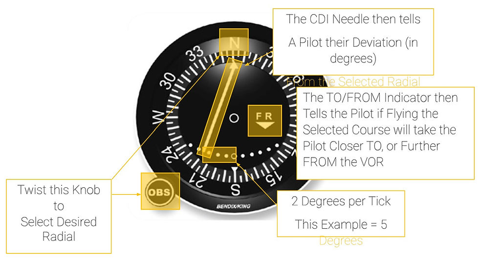
The TO or FROM indication
When will the TO/FROM Indicator switch indications?
If Crossing over the VOR: At Station Passage
If not Crossing over the VOR: At 90 Degrees from the Selected Radial

Tracking
Tune the VOR frequency and check the identifiers to verify you are receiving the desired VOR.
Rotate OBS to center CDI to a “TO” indication. If centered with a “FROM” indication, rotate another 180°.
Turn to the heading indicated on the VOR azimuth dial or course selector, to track directly to the station in a no wind situation.
If there is a crosswind, and the heading is maintained, the aircraft will drift off course. Alter the heading to return to the desired radial, and once the CDI is centered and the aircraft is back on the radial, crab into the wind to establish wind correction. Trial and error will establish the necessary heading to maintain the desired track.
Upon arriving and passing the VOR station, the “TO” indication will change to a “FROM” indication.
Reverse sensing
If flying toward a VOR with a “FROM” indication, the CDI will indicate opposite the direction it should. If the plane drifts right of course, the needle will move right. The same applies when flying from a station with a “TO” indication.
VOR Tips
One is to always identify the station positively by its code or voice ID.
When tracking to a station determine the inbound course and use it.
Don’t succumb to the temptation to just twist the OBS to re-center the VOR.
If done too much the aircraft will describe a spiral path to the station until the winds are directly in line with the course being flown, which is very sloppy flying.
When flying TO a station always use a TO indication, and the reverse when flying away, thus avoiding the possible confusion of reverse sensing.
Distance Measuring Equipment (DME)
Consists of an ultra-high frequency (UHF) navigational aid used in conjunction with VOR/DMEs and VORTACs
measures the distance between an aircraft and an associated VOR in “Slant Range Distances.”
Not all aircraft are equipped with DME and use GPS Distances instead.
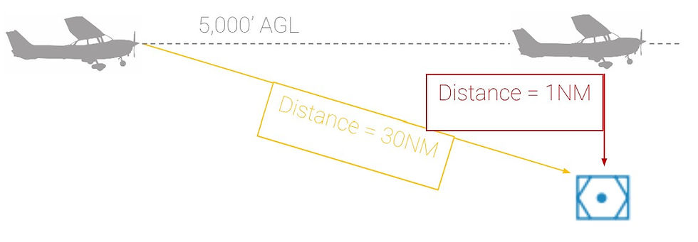
Slant Range Distance
Sending out a radio signal to the associated NavAid and the NavAid bouncing that signal back to the aircraft that sent it
The aircraft’s on-board DME Receiver then calculates the time it took to receive the bounced signal and relays the necessary distance information to the pilot
Errors
The closer the aircraft gets to the NavAid, the less accurate the DME will be.
DME is most accurate when the aircraft is further from the NavAid and at lower altitudes. This is because it “flattens” the slant.
GPS Distances
Modern aircraft are not equipped with Traditional DME and are rather equipped with GPS Distance
measures the “Straight Line Distance” between the LAT/LONG of the aircraft and the LAT/LONG of the NavAid.
Satellite-based navigation
Satellite-based navigation systems include:
GPS — Global Positioning System
RAIM — Receiver Autonomous Integrity Monitoring
WAAS — Wide Area Augmentation System
LAAS — Local Area Augmentation System
Global positioning system (GPS)
Over the last few decades GPS technology has started to pervade our live, including our flying. Satellite based navigation have a number of components which include the GPS satellite system itself, the Wide Area Augmentation System (WAAS), — Receiver Autonomous Integrity Monitoring(RAIM) and the Local Area Augmentation System (LASS).
The broader GPS system is composed of three major elements. The Space Segment, the Control Segment, and the User Segment.
Space Segment
This segment is currently composed of 31 satellites each approximately 12,000 nm above the earth.
The US is committed to maintain 24 operational satellites 95% of the time arranged
so that at any time 5 are in view to any receiver (with 4 being the minimum necessary for operation).
Each satellite orbits the earth in approximately 12 hours and are equipped with extremely stable atomic clocks each transmitting a unique code/nav message.
These satellites broadcast in the UHF frequency range which reduces the impact of weather on the signals.
These signals are line-of-sight, so a satellite must be above the horizon to be "visible" to the GPS receiver.
How many satellites does our GPS receiver need to be in contact with?
Calculate a 2D (LAT/LONG) Position = 3
Calculate a 3D (LAT/LONG and Altitude) = 4
Calculate RAIM = 5
Fault Detection and Exclusion = 6
Function of the GPS
Based on the concept of ranging and triangulation from a group of satellites in space that act as precise reference points
DRAW out
GPS receiver measures distance from a satellite using the travel time of a radio signal.
Each satellite transmits a specific code,
called a course/acquisition (CA) code
Satellite position,
The GPS system time,
Health and accuracy of the transmitted data
Pseudo-range
Knowing the speed at which the signal traveled (approximately 186,000 miles per second) and the exact broadcast time,
The distance traveled by the signal can be computed from the arrival time
Control Segment
This segment consists of a
master control station
five monitoring stations,
three ground antennas.
The monitoring stations and ground antennas are distributed around the globe to allow continual monitoring and communications with the satellites.
Updates and corrections to the nav message broadcast are uplinked as the satellites pass over the ground antennas.
User Segment
This consists of all components associated with the GPS receiver. These can range from simple portable hand-held receivers to those permanently mounted in the aircraft. The receiver uses the signals from the satellites to calculate position, velocity, and precise timing to the user.
To solve for a location the GPS receiver uses the calculated distance and position information from the satellite from at least four satellites to yield a 3-D fix. This fix includes latitude, longitude, and altitude. VFR navigation with GPS can be a simple as selecting a destination and tracking the course (i.e. the Magenta Line). With GPS the course deviation is linear so that there is no increase in sensitivity when approaching a waypoint. It can be extremely tempting to rely exclusively on GPS, but never rely on one means of navigation.
RAIM
Receiver Autonomous Integrity Monitoring
Is the capability of a GPS receiver to perform integrity monitoring on itself by ensuring available satellite signals meet the integrity requirements for a given phase of flight.
Minimum of 5 satellites
FDE (Fault Detection Exclusion) requires 6 minimum
Excludes a failed satellite from the position solution
Without RAIM, the pilot has no assurance of the GPS position integrity. RAIM provides immediate feedback to the pilot
IF unable gps will indicate
LOI
Loss of GPS Integrity
How many satellites does our GPS receiver need to be in contact with?
Calculate a 2D (LAT/LONG) Position = 3
Calculate a 3D (LAT/LONG and Altitude) = 4
Calculate RAIM = 5
Fault Detection and Exclusion = 6
GPS Modes
Utilize three different Sensitivity Modes.
This is referring to the sensitivity of the CDI Needle and how far a pilot can be off a chosen course before the CDI has gone full deflection
En-Route Mode: When more than 30NM from both the Departure and Destination Airports.
Sensitivity = 2NM either side of course centerline.
4NM total
Terminal Mode: When within 30NM of either the Departure or Destination Airports.
Sensitivity = 1NM either side of Centerline.
Approach Mode: When within 2NM of the FAF At the Destination Airport.
Sensitivity = 0.3NM either side of Centerline.
GPS Errors
Atomic Clock: An Atomic Clock is a clock that is accurate to the 1 Billionth of a Second.
Therefore, if a time code sent by a GPS Satellite is 5 Billionths of a second inaccurate then our GPS position can be off by up to 5 feet.
Satellite Position: There is a lot of space junk also orbiting the Earth.
If a piece of this space junk knocks a satellite off its normal orbiting position then our GPS Receiver may receive faulty information from that satellite.
The Atmosphere: The Ionosphere and Troposphere can bend and delay GPS Radio Signals from reaching our on-board GPS Receivers.
This can result in both time code and position errors
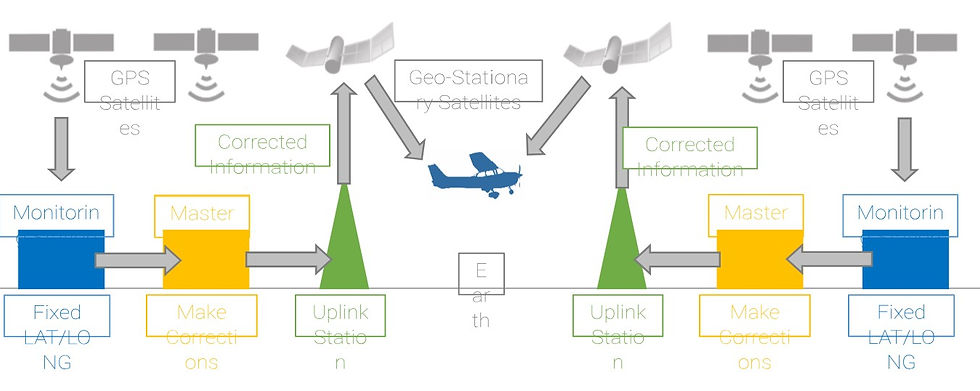
WAAS (AIM 1-1-18)
to improve the accuracy, integrity, and availability of GPS signals. WAAS will allow GPS to be used, as the aviation navigation system, from takeoff through approach when it is complete.
installation of 3 GEO satellite, 2 operational control centers
Signals from the GPS satellite constellation are monitored by WAAS ground-based stations,
to determine satellite clock and position corrections.
Two master stations, located on either coast,
collect data from the reference stations and create a GPS correction message.
The correction message is prepared and
uplinked to a geostationary satellite via a ground uplink station.
This correction accounts for GPS satellite orbit and clock drift, plus signal delays caused by the atmosphere and ionosphere.
The corrected differential message is broadcast through 1 of 2 geostationary satellites, or satellites with a fixed position over the equator.
The information is compatible with the basic GPS signal structure, which means any WAAS-enabled GPS receiver can read the signal.
The Wide Area Augmentation System (WAAS) and Local Area Augmentation System
(LAAS) were deployed to achieve a higher degree of position precision for the GPS system. This improves the position calculation enough such that the GPS can be used for precision approaches. In the worst case WAAS precision is accurate to 25 feet 95% of the time. Like GPS the WAAS includes Space, Control, and User segments.
LAAS/GBAS
The LAAS/ GBAS is very similar to WAAS, but relies more on ground stations for signal correction and improvement. However, it is considered to be less cost effective than WAAS, but is also considered to be capable of handling Category III approaches.
Instrument landing System (ILS)
Introduction
Used to execute a precision instrument approach procedure or precision approach
Components
Localizer (Horizontal Guidance)
Glideslope (Vertical Guidance)
Marker beacons
Lighting system
Localizer
The Localizer sends out 2 signals
90 hz left
150 hz right
The airplane must be receiving equal parts of both the 90hz and 150hz signals
If the airplane is receiving more of 1 signal than the other, the pilot will notice an off-course indication on his/her HSI or OBS
Location
The back end of runway (departure end)
Width of localizer (700 ft at approach end of runway)

Glideslope
Similar to localizer
Put on side
Near the approach end of runway
False glideslope
This can create false glideslopes, which are often at 9 degree and 12 degree angles to the runway.

Marker Beacons
Alerts a pilot to his/her location along the final approach course.
There are 3 types of Marker Beacons
Outer Marker (OM)
Identifies glideslope intercept or the Final Approach Fix
Middle Marker (MM)
Identifies decision height
Inner Marker (IM)
Identifies decision height for a CAT II ILS
Approach Light System FAR 91.175(c)
They are intended to aid the pilot in transitioning between Instrument Flight to Visual Flight and a subsequent landing.

Transponder
Due every 24 calendar months. Required for the aircraft to fly in Transponder Airspace.
Types
Mode A
Will only show the selected squawk code on the controllers screen
Mode C
Combines the basic details of Mode A with pressure altitude giving ATC controllers a read-out of an aircrafts altitude on their screen
Mode S
Mode c with aircraft information and ADS-B
Airspace
Class A Airspace
Class B Airspace
Class C Airspace
Mode C Veil Around Class B Airspace
Above 10,000’ MSL
Except when Below 2,500’ AGL
Autopilot
Autopilot is an automatic flight control system that keeps an aircraft in level flight or on a set course. It can be directed by the pilot, or it may be coupled to a radio navigation signal.
FMS (The Flight Management Systems)
A system that automates the tasks of managing the onboard navigation systems
FMS can be thought of as a computer with a large database
Airport and NAVAID locations and associated data
Aircraft performance data
Airways
Intersections
DPs
STARs
Can quickly define a desired route from the aircraft’s current position to any point in the world
Perform flight plan computations
Display the total picture of the flight route to the crew.
Indicates position, track, desired heading, groundspeed and position relative to desired track
Conclusion
One ground-based navigational system
Distance Measuring Equipment (DME)
Satellite-based navigation
Instrument landing System (ILS)
Transponder
Autopilot
(Questions to assess student)
How does a VOR work?
DME?
How does the ILS work?
What about lighting?
HW: look over IFH